Rigid transformations
In mathematics, a rigid transformation (also called Euclidean transformation or Euclidean isometry) is a geometric transformation of a Euclidean space that preserves the Euclidean distance between every pair of points. In the context of pylinac rigid transformations are used to place ROIs and include rotations and translations while reflections are intentionally left out.
In 2D
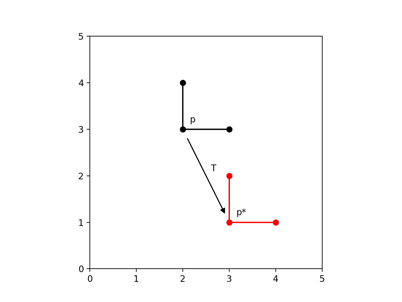
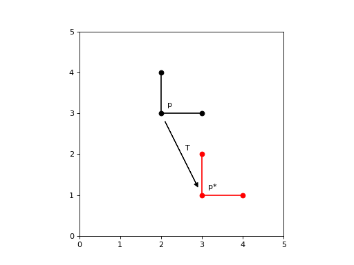
Translations
In Euclidean geometry, a translation is a geometric transformation that moves every point of a figure, shape or space by the same distance in a given direction.
(Source code, png, hires.png, pdf)
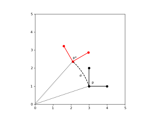
Rotations
In Euclidean geometry, a rotation is a geometric transformation that turns every point of a figure, shape or space around a fixed point through a specified angle and in a specified direction
(Source code, png, hires.png, pdf)

Pose
In 2D geometry, a pose (or transform) is a combination of a translation and a rotation:
The way to define this transformation is by using 3x3 matrices:
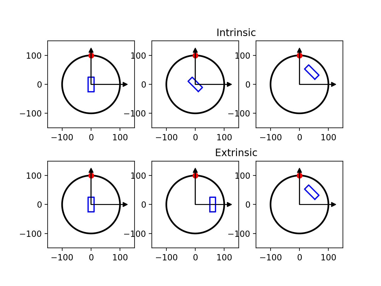
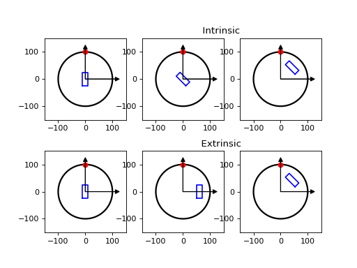
Coordinate system and order of operations
Since matrix multiplications are not commutative, the order by which each individual transformation is applied matters. Furthermore the concept of transformation also depends on the frame of reference of the user. Two frames of reference can be defined:
Extrinsic (space‑fixed) coordinates: the axes stay put in the “world” frame, and each transformation is performed about one of those fixed axes.
Intrinsic (body‑fixed) coordinates: the axes ride along with the object, i.e. the next transformation is with respect to the new axes.
Let’s look at some examples:
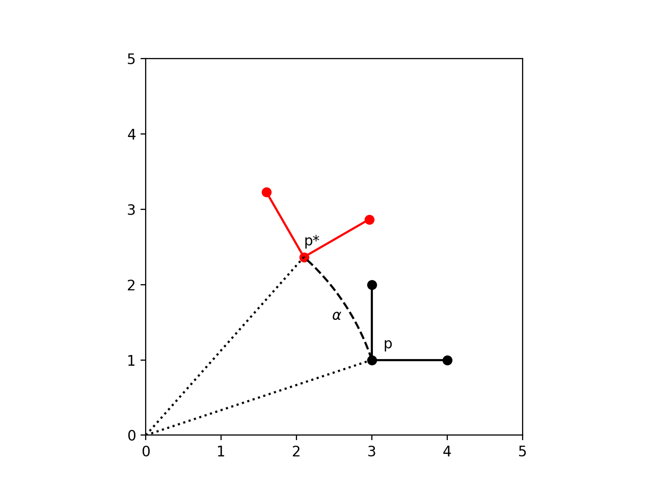
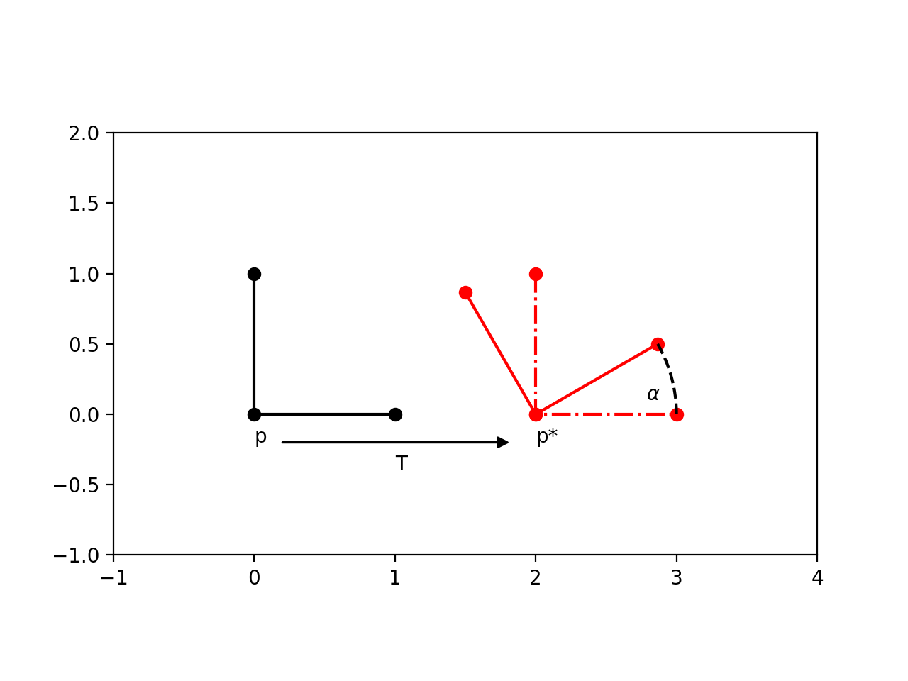
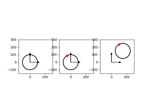
First rotation then translation (extrinsic coordinates):
(Source code, png, hires.png, pdf)
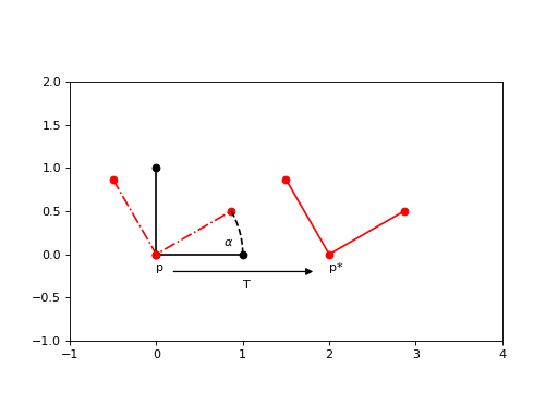
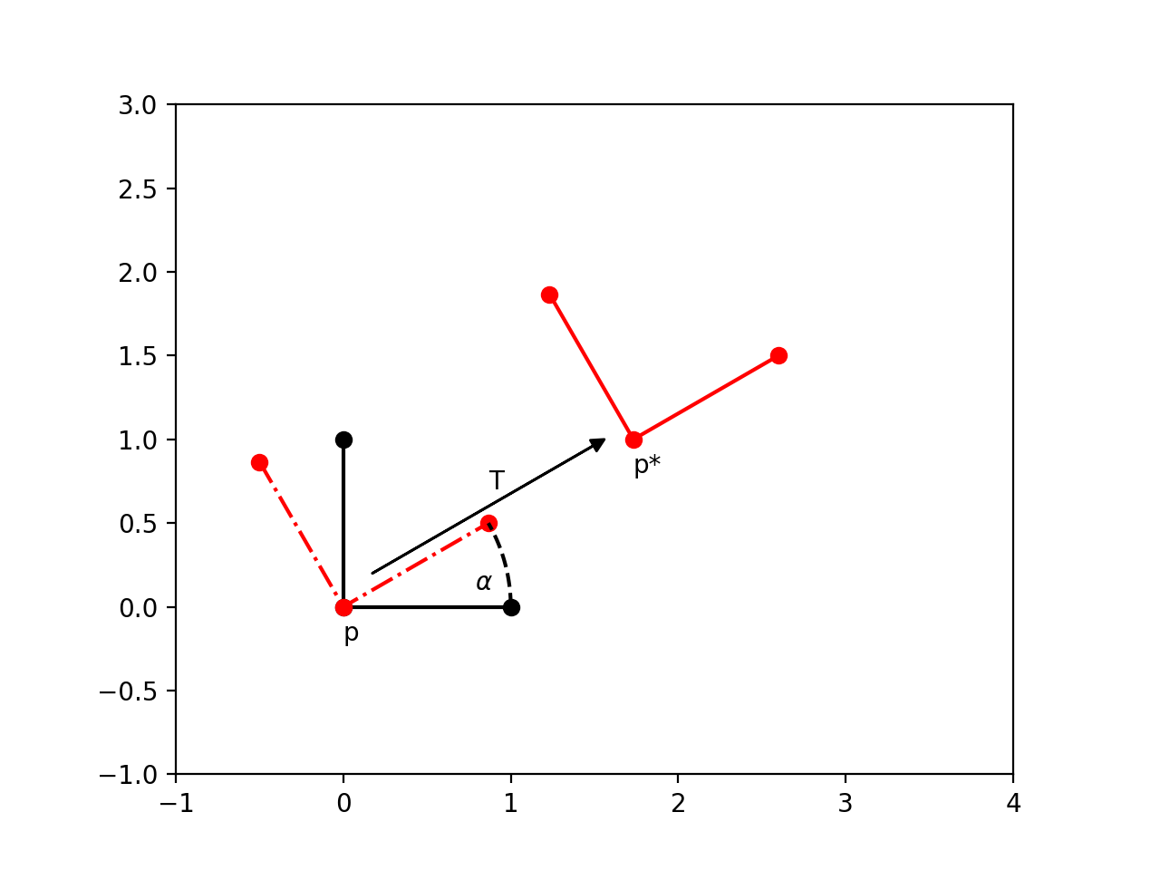
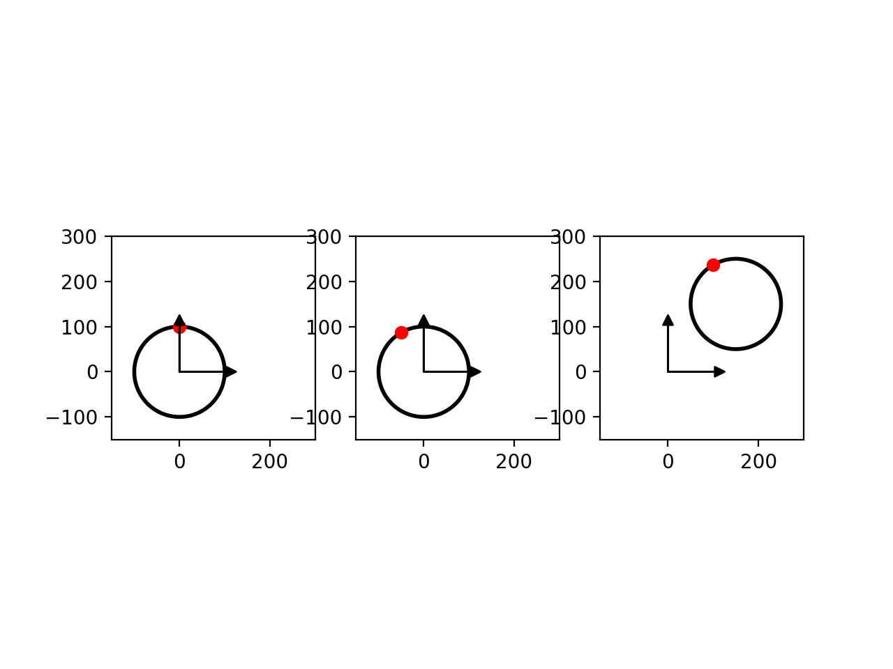
First translation then rotation (extrinsic coordinates):
(Source code, png, hires.png, pdf)

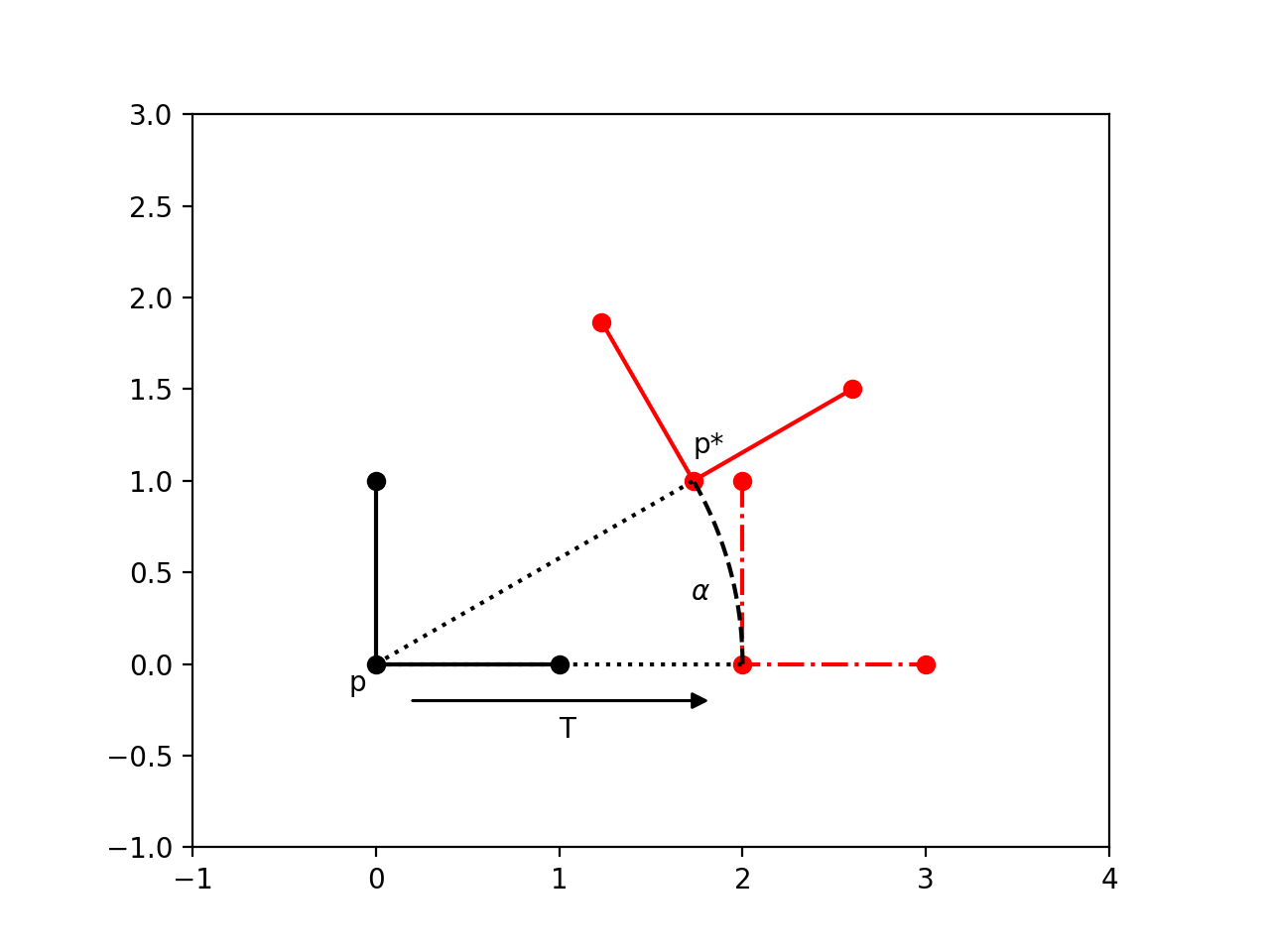
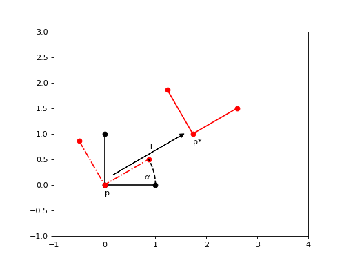
First translation then rotation (intrinsic coordinates):
where Rotation' represents the rotation in the intrinsic frame of reference
Note
(Source code, png, hires.png, pdf)

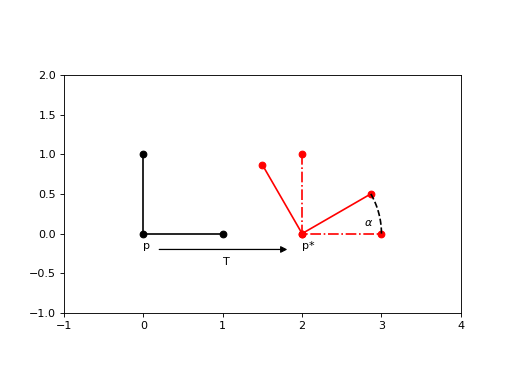
First rotation then translation (intrinsic coordinates):
where Translation' represents the translation in the intrinsic frame of reference
Note
(Source code, png, hires.png, pdf)
Corollary:
where ' represents the transformation in the intrinsic frame of reference.
Multiple ' are used to represent that the intrinsic frame of reference changes with each previous transformation.
In code
scikit-image.transform can be used to implement these transformations using the following conventions:
EuclideanTransform(r,t): performs the rotation first, then the translation, in extrinsic coordinates
tform = EuclideanTransform(rotation=r, translation=t)
# or
tform = EuclideanTransform(translation=t, rotation=r)  # order of parameters is irrelevant
tform1 + tform2: the ‘+’ operator is a magic method that performs EuclideanTransform1 first, then EuclideanTransform2, in extrinsic coordinates
tform = tform1 + tform2
# or
tform = EuclideanTransform(matrix = tform2.matrix @ tform1.matrix)  # same as above
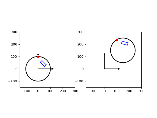
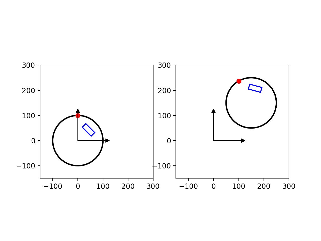
Example of ROI placement using rigid transformations
Here is an example for ROI placement in a scanned slice image of the Catphan phantom. First we do the ROI to phantom transform, then we do the phantom to image transform. We then combine these two transforms to produce the final transform ROI to image.
- ROI placement with respect to nominal phantom:
1.1. Let’s start using an ROI with width = 40 and height = 20
1.2. Then rotate the ROI by 45 deg
\[Tf_1 = R(45°)\]tform_1 = tform_r_45 = EuclideanTransform(rotation=np.deg2rad(45))
1.3. Then translate in the radial direction by 60 (intrinsic translation)
\[Tf_2 = T'(60) * Tf_1 = Tf_1 * T(60) = R(45°) * T(60)\]tform_t_60 = EuclideanTransform(translation=[60,0]) tform_2 = tform_t_60 + tform_1 = tform_t_60 + tform_r_45
1.4. This is the ROI placement with respect to nominal phantom
\[Tf_{roi}^{phantom} = Tf_2 = R(45°) * T(60)\]tform_roi_phantom = tform_2 = tform_t_60 + tform_r_45
(Source code, png, hires.png, pdf)
- Phantom placement with respect to image:
2.1. Let’s start with a centered (nominal) phantom
2.2. Then roll the phantom by 30 deg (exaggerated for visual purposes only)
\[Tf_1 = R(30°)\]tform_1 = tform_r_30 = EuclideanTransform(rotation=np.deg2rad(30))
2.3. Then translate the phantom to the image center (extrinsic translation)
\[Tf_2 = T(c) * Tf_1\]c = [150, 150] tform_t_c = EuclideanTransform(translation=c) tform_2 = tform_1 + tform_t_c = tform_r_30 + tform_t_c
2.4. This is phantom placement with respect to image coordinates
\[Tf_{phantom}^{image} = Tf_2 = T(c) * R(30°)\]tform_phantom_image = tform_2 = tform_r_30 + tform_t_c # same as tform_phantom_image = EuclideanTransform(rotation=np.deg2rad(30), translation=c)
(Source code, png, hires.png, pdf)
- ROI placement with respect to image:
3.1. The ROI transformation to global are the cascading transformations (extrinsic operation)
\[Tf_{roi}^{image} = Tf_{phantom}^{image} * Tf_{roi}^{phantom}\]tform_roi_image = tform_roi_phantom + tform_phantom_image
(Source code, png, hires.png, pdf)